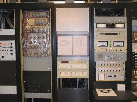
O.K. Here are the first four racks. Starting on the left, half way out of view is the rack that contains the transmitter switching panel. This panel selects which of the three transmitters will be on the air or into the dummy load, which directional pattern we are using, day or night, or in case of an emergency or for tower work, it allows us to feed tower one or two by itself at a lower power.
The next rack is full of relays to interface our remote controls to other equipment. Rack three has a Potomac Instruments RC16 remote control. The remote control allows us to control the transmitters remotely from our studio. Clever name remote control.
Rack four contains, from the top, monitor switching panel, a Belar AMM-1 modulation monitor, a phase monitor for the towers, a intercom, and another remote control. The modulation monitor uses two meters to let us know how loud the audio is on the air . The phase monitor tells us what the phase and power amounts are of the signals going to each tower. We are required by the FCC to keep these at a certain amount to insure that our directional pattern is sending the on air signal in the right directions. The intercom allows us to talk to each tower base when we are doing maintenance. The TFT remote control works in parallel with the Potomac remote control. We use two in case of a failure of one or the other.
Questions or comments about the tour?
![]()
Updated 9/2/98
KCBS-KLLC ENGINEERING DEPT